Manual.ly Logo

Doepke DFA 3 024DC Manual

0.0 · 0 Ratings

PDF manual · 2 Pages

English

M: OA-GPT-5-NAN
page

/ 2

Loading...
43bdce2d95d5cbfe856dec9fd154d76b2726 page 2
Technical data
Product name DFA 3 024DC-0 DFA 3 024DC-3
Switch drive design Motor drive
Maximum DFS rated current 

attempts
 Yes
 Yes
 
Mounting side Left
Operating voltage (DC) 
Current consumption (DC) 
Output status display
 Luminescent panel (multi-coloured)
Control input
 
 
 
Switching output
Design Semiconductor
 
 
 
Top screw-type terminal
(control input, switching output)
 
 
General data
Duty cycle Continuous operation
 – 
Positioning Optional
Ambient temperature 
Permissible humidity 
Housing type Distribution board housing
Mounting type 
Housing material Polycarbonate (PC)
Protection class 
Width × height × depth 
Installation depth 
Module widths
Design regulations/standards


Warranty
       
warranty for the duration of the statutory warranty period from
-
cable to damage incurred during transport or caused by short-
    
-
        


DFA 3 024DC-0 optical signals (luminescent panel with RGB LED):
Status RGB LED
DFA: deactivated 
DFA: activated



 Blue


Green
DFA: electromechanically locked Flashing green
Incorrect operating voltage during commissioning Alternating red/green/blue
Actuating the luminescent panel switch Yellow
DFA 3 024DC-3 optical signals (luminescent panel with RGB LED):
Status RGB LED
DFA: deactivated 
DFA: activated




(no automatic switch-on)
Blue


Green

Waiting time until automatic switch-on
Flashing blue
DFA: blocked Flashing white
DFA: electromechanically locked Flashing green
Incorrect operating voltage during commissioning Alternating red/green/blue
Actuating the luminescent panel switch Yellow
-
     

       -

        


! Risk of crushing when automatically switched on!
DFA 3 024DC-0 and DFA 3 024DC-3 acoustic signals
Status Tone sequence
Before DFA switch-on or reset 
 
 
Dimensional drawing
43,7
73
17,8
89
6
Operation on the device
1
3
2
1
3
1
—
        
         

2
—



3
—
Pushing the luminescent panel down electro mechanically

-

Power supply
-



Control inputs


Switch on (terminal on)
       

        
           

Switch off (terminal off)

 -
nates green after the switch has been actuated to indicate


Switching output
Feedback: RCCB not on (terminal RM/FB)

which has a load capacity of 200 mA and means that the re-

Wiring diagram
on
0 V
RM
FB
+24 V
0 V
RCCB not switched on
+24 V/200 mA
switch off
switch on
off
+24 V
Installation and operating instructions
DFA 3 024DC-0 and DFA 3 024DC-3 remote actuators
     -
scribe the installation and commissioning for the

        -
       -
nect devices of this type due to the considerable po-


Scope of delivery

Intended use
       
       

      


and the device needs to be reset to recommission remote actua-

-


        -
connection is only permitted in areas that can only be accessed
by persons who have electrical training and trained electri-
        
power distributors or on plants in dry indoor conditions as per

Installation and commissioning
     
    


by the drive lever of the DFA 3 and both devices are securely


1
2
3
1
DFA 3
V DFA 3 mounted on DFS 4
(1) snap-on hooks, (2) drive lever, (3) toggle
Doepke

|

|

DE EN

Chat with your Doepke DFA 3 024DC manual using AI

Get instant AI answers from your Doepke DFA 3 024DC manual

Ask anything about the Doepke DFA 3 024DC. Answers come from this manual, with the pages they are based on.

Ask a Question

0/1000

Do you recommend DFA 3 024DC?

Yes No

Frequently Asked Questions

A

The DFA 3 024DC is a motorised remote actuator for residual-current circuit breakers (RCCBs), enabling remote on/off switching, local push-button operation via a luminescent disc, status signalling and feedback to control systems.

Is this answer helpful?

A

Both share the same mechanical and signalling features; the DFA 3 024DC-3 adds an automatic three-attempt reclose function that tries to restore the RCCB after a trip, with visible and audible indicators during retry intervals.

Is this answer helpful?

A

The unit requires a 24 V DC supply for operation. Control inputs use +24 V logic to switch on/off; wiring is through the supplied five‑pole connector and top screw terminals for easy panel installation.

Is this answer helpful?

A

It features RGB visual status (activated, blocked, locked, incorrect voltage, waiting for reclose) and acoustic warnings before automatic switching. An electromechanical lock and blocking state prevent unsafe reclosure, and a feedback contact reports if the RCCB did not close.

Is this answer helpful?

A

The DFA 3 is designed for compatibility with Doepke RCCBs and similar breakers up to specified rated currents (installation beside the RCCB is required). Confirm mechanical fit and electrical interface for your breaker model before retrofit.

Is this answer helpful?

A

The feedback (RCCB not on) output can drive small indicator loads, typically up to around 200 mA. For larger loads or PLC inputs requiring different voltages, use an intermediary relay or interface module.

Is this answer helpful?

A

Installation and commissioning must be performed by electrically trained or qualified personnel, following local regulations and the manufacturer’s instructions to ensure safe mounting, correct wiring and proper testing.

Is this answer helpful?

M: OA-GPT-5-NAN

Advantages and Disadvantages

Advantages

  • Compact 1 TE design saves space in distribution boards and is easy to retrofit.
  • Clear RGB visual signalling plus acoustic tones improve onsite awareness and diagnostics.
  • DFA 3 024DC-3 offers three automatic reclose attempts to restore power after transient trips.
  • Semiconductor switching output and top screw terminals simplify integration with control systems.
  • Electromechanical lock and blocking states prevent unsafe automatic reclosure, enhancing safety.
VS

Disadvantages

  • Requires 24 V DC supply and appropriate control wiring, adding installation complexity.
  • Feedback output limited to modest loads (around 200 mA) — may need interface relays for larger loads.
  • Automatic reclose can pose crushing risk during switch-on — careful signage and procedures required.
  • Installation and commissioning must be performed by trained electrical personnel, limiting DIY use.
  • Some states require manual reset after faults, which can delay automatic restoration in certain scenarios.
M: OA-GPT-5-NAN

Product Specification

Type

Other

M: OA-GPT-54-NAN

Product Description

Doepke Remote Drive — DFA 3 024DC (24 V DC, 1 TE)

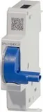
The Doepke Remote Drive DFA 3 024DC is a compact, motorised remote actuator designed for safe, reliable operation of RCCBs up to 125 A. In a single-module (1 TE) housing and powered by 24 V DC, the DFA 3 offers remote on/off control, visual and acoustic status signalling, and a semiconductor switching output for integration into control circuits. Two variants are available: DFA 3 024DC-0 and DFA 3 024DC-3 — the latter adds an automatic three-attempt reclose function to restore power after transient trips.

Engineered for installation beside a residual-current circuit breaker, the actuator mounts easily in distribution boards and is mechanically coupled to the breaker via snap hooks and a drive lever. Operation is straightforward: a multi-colour luminescent status disc with RGB LED provides clear state feedback (activated, deactivated, blocked, locked, incorrect supply voltage, waiting for reclose) and also serves as a push actuator. Acoustic tones warn prior to automatic switching and during key states to enhance on-site safety.

The DFA 3 supports remote switching inputs (on/off) and provides a feedback contact that signals if the RCCB has not closed (RCCB not on). Top screw terminals simplify wiring; the control interface accepts a +24 V control logic and the feedback output is rated to drive small indicator loads (typically up to 200 mA). Designed for continuous duty, the unit operates across typical indoor ambient conditions and features a polycarbonate housing suited for distribution panels.

DFA 3 024DC-3 specific features include three automatic reclose attempts with visible blinking codes during retry intervals and audible warnings to alert personnel — a practical feature in systems where nuisance trips may occur and rapid restoration is desired without immediate manual intervention. The device’s electromechanical lock and blocking states prevent unsafe reclosure and require manual reset when necessary.

Installation and commissioning must be performed by electrically trained personnel. The actuator is intended for retrofit or new installations in dry indoor switchgear and power distribution boards. Its compact footprint, clear signalling and optional automatic reclose make the DFA 3 a useful accessory for improving safety, diagnostics and remote control of RCCB-protected circuits.

Notes:

  • Two model options: DFA 3 024DC-0 (basic remote drive) and DFA 3 024DC-3 (with three automatic reclose attempts).
  • Visual status via RGB luminescent disc; push action available for local control.
  • Feedback contact indicates RCCB not closed; load capacity ~200 mA.
  • Designed for mounting left of the RCCB; polycarbonate housing for panel integration.
M: OA-GPT-5-NAN

© Copyright 2026 Manual.ly