

Cisco Nexus 92300YC Manual
PDF manual · 60 Pages
English



Quick check
Incorrect answer, please try again.
Chat with your Cisco Nexus 92300YC manual using AI
Get instant AI answers from your Cisco Nexus 92300YC manual
Ask anything about the Cisco Nexus 92300YC. Answers come from this manual, with the pages they are based on.
Nexus 92300YC Maintenance Schedule
Clean connectors regularly depending on the environment. Clean if exposed to dust or accidentally touched.
Inspect routinely for dust and damage. If suspect damage, clean and inspect under a microscope.
Ask a Question
Do you recommend Nexus 92300YC?
Yes NoFrequently Asked Questions
It is designed for top-of-rack data center deployments where high port density, flexible uplinks, and reliable management are needed. It fits access, aggregation, and fast-growth server environments.
Is this answer helpful?
The 48 SFP28 downlinks can run at 10G or 25G, and the 18 QSFP28 uplinks can operate at 40G or 100G. This makes it useful for mixed-performance network designs.
Is this answer helpful?
All fan and power supply modules must use the same airflow direction to keep the switch properly cooled. If airflow is mismatched, the unit can overheat and shut down.
Is this answer helpful?
Yes, in many cases one fan module or one power supply can be replaced during operation. The replacement must match the installed airflow direction, and airflow changes across the whole chassis require shutdown.
Is this answer helpful?
You need a compatible rack or cabinet, proper grounding, enough clearance for cables and airflow, and suitable power circuits. Site temperature, humidity, and EMI conditions also matter.
Is this answer helpful?
Initial access is usually done through the console port using a terminal emulator. After basic setup, the management port can be used for ongoing network administration.
Is this answer helpful?
Verify Cisco compatibility for the exact transceivers, adapters, and cables you plan to use. The switch supports specific port types, and some QSFP28 ports may need adapters for SFP-based modules.
Is this answer helpful?
Advantages and Disadvantages
Advantages

- High-density design with 48 SFP28 and 18 QSFP28 ports for flexible access and uplink scaling.
- Supports 10/25G downlinks and 40/100G uplinks, making migration paths easier in mixed environments.
- Redundant power and fan modules improve uptime and simplify maintenance during operation.
- Detailed site and rack guidance helps reduce installation mistakes and cooling issues.
Disadvantages

- All fan and power modules must share the same airflow direction, which limits mix-and-match flexibility.
- Power, rack, and clearance requirements are strict and must be planned before deployment.
- Some component swaps require careful timing and may need a full shutdown when changing airflow direction.
- Transceiver and cable compatibility must be checked closely to avoid installation or performance issues.
Product Specification
Function
Switch, SAN-Switch
Type
Standalone, Rackmount (via mounting brackets)
Network ports
48x SFP28, 18x QSFP28
Speeds
48x SFP28 (1G/10G/25Gb/s), 18x QSFP28 (40G/100Gb/s)
PoE
N/A
Backplane
6.0Tb/s, 4.75Gp/s, 30MB packet buffer, 92k Mac addresses
Officially supported standards
IGMP
Configuration
Web interface, Console, serial (RJ-45, USB-A 2.0, rear), Network (SFP, RJ-45, dedicated, 10/100/1000Base-T, rear)
Cooling
active, 4x fans (1.57in, 1x hot-plug each)
Dimensions (WxHxD)
17.24x2.01x22.28in, 1.25U
Weight
18.52lb
Color
silver
Special features
Metal housing, removable mounting brackets, firmware updates possible, redundant power supply (redundant power input), 2x hot-plug power supply units
Manufacturer's warranty
one year
Product Description
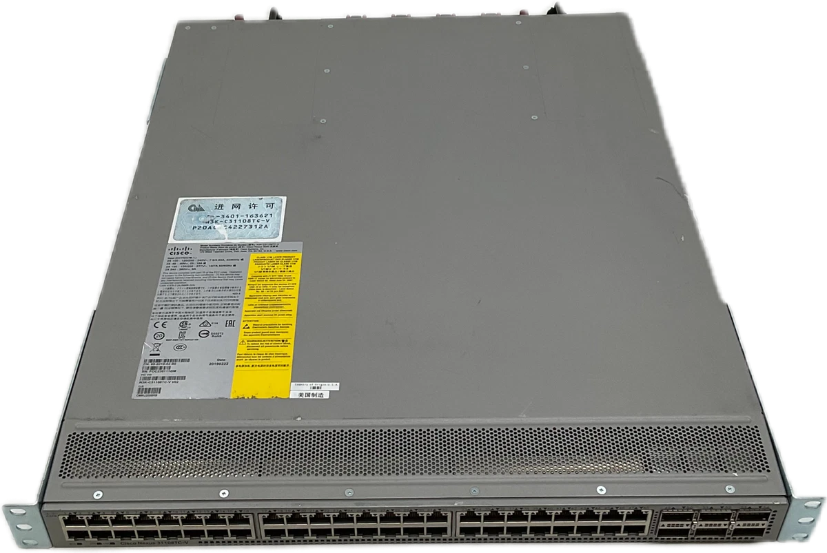
Cisco Nexus 9200 Rackmount 25G Managed Switch, 48x SFP28, 18x QSFP28
The Cisco Nexus 9200 Rackmount 25G Managed Switch, 48x SFP28, 18x QSFP28 Manual reflects a high-density data center switch built for modern top-of-rack deployments. With 48 SFP28 downlink ports and 18 QSFP28 uplinks, this platform is designed to handle fast server access, aggregation, and spine connectivity in compact rack environments. It balances port flexibility with operational discipline, making it a strong fit for growing enterprise networks that need speed without sacrificing control.
A key strength of this switch is its adaptable port design. The 48 SFP28 interfaces can operate at 10G or 25G, while the 18 uplink ports support 40G or 100G connectivity. That gives teams room to scale access layers, support mixed workloads, and simplify migration paths as bandwidth demands rise. The layout is also optimized for cabling, which helps reduce clutter and improve day-to-day maintenance.
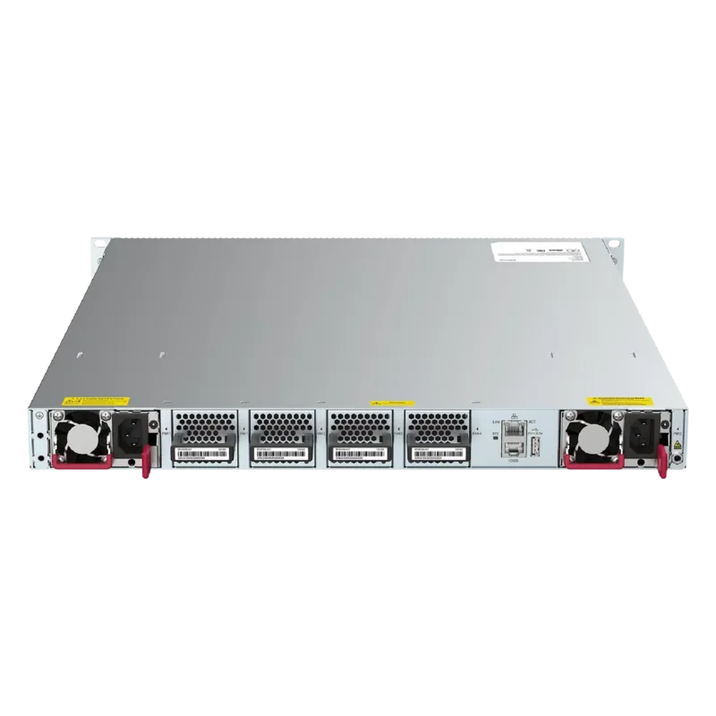
The hardware is built with practical data center reliability in mind. Dual power supplies and four fan modules provide redundancy and service continuity, while airflow options support either hot-aisle or cold-aisle deployments. The guide emphasizes matching airflow direction across all modules, which is essential for stable cooling and uninterrupted operation. This makes the switch especially suitable for environments where thermal planning matters just as much as throughput.
Installation and site preparation are treated as first-class concerns. The guidance covers rack depth, clearance, grounding, temperature, humidity, altitude, EMI, and power planning in detail. That level of structure helps network teams avoid common deployment mistakes and set up the system correctly from the start. It also shows that Cisco expects this switch to live in demanding, production-grade environments.
Beyond installation, the switch supports routine maintenance with replaceable fans and power supplies, clear LED indicators, and straightforward console and management access. For operators, that means faster troubleshooting and better visibility during boot, service, or recovery events. In short, this is a switch designed not just for speed, but for dependable operations over time.
Notes
- Keep all fan and power modules aligned to the same airflow direction.
- Use grounded racks and dedicated power circuits whenever possible.
- Match rack depth and cable clearance before installation.
- Follow the transceiver and cable compatibility guidance for best results.
Search for 67,706 Manuals online


Type-in Brand or Model