
Cisco Aironet AIR-PWRINJ1500-2= Manual
PDF manual · 10 Pages
English



Quick check
Incorrect answer, please try again.
Chat with your Cisco Aironet AIR-PWRINJ1500-2= manual using AI
Get instant AI answers from your Cisco Aironet AIR-PWRINJ1500-2= manual
Ask anything about the Cisco Aironet AIR-PWRINJ1500-2=. Answers come from this manual, with the pages they are based on.
Ask a Question
Do you recommend Aironet AIR-PWRINJ1500-2=?
Yes NoVideo Manual
How to Set Up an Ethernet Switch | Internet Setup
Frequently Asked Questions
The injector supplies a regulated 56 VDC output with a tolerance of 54–57 VDC and a maximum current of 1.43 A, delivering up to 80 W over all four wire pairs to compatible access points.
Is this answer helpful?
Use shielded CAT5e or higher between the switch and injector, and shielded outdoor-rated CAT5e or higher (0.20–0.35 inch diameter) between the injector and AP. Cable gauge must be at least 26 AWG for telecommunication cords.
Is this answer helpful?
Yes. The Ethernet cable from the injector to the AP must be at least 10 ft (3 m) and no more than 140 ft (42 m). The total switch-to-AP distance must not exceed 100 m (328 ft).
Is this answer helpful?
Three LEDs indicate status: AC POWER turns solid green when AC is present; AP POWER turns solid green after successful discovery and when powering the AP; FAULT turns solid red if a fault is detected during discovery or power-up.
Is this answer helpful?
No. The unit must be mounted vertically to meet safety requirements and is not suitable for installation in building environmental air spaces. Follow local jurisdiction mounting rules and use appropriate fasteners.
Is this answer helpful?
Yes. Cisco recommends grounding after installation using a UL-listed ring lug and a minimum 12 AWG (2.5 mm²) copper green/yellow conductor rated for 90°C, attached to a permanent building ground.
Is this answer helpful?
Yes. When the power injector supplies power to the access point, the AP's PoE-out port is disabled and cannot provide downstream PoE to other devices.
Is this answer helpful?
Advantages and Disadvantages
Advantages

- Provides 56 VDC PoE+ over shielded RJ-45 to power Aironet APs up to 80 W across four pairs.
- Wide input range (100–240 VAC) and broad operating temperature (-40 to 55°C) for varied environments.
- Simple installation with TO SWITCH and TO AP RJ-45 ports and clear LED status indicators.
- Supports Gigabit Ethernet (10/100/1000Base-T) and requires standard shielded CAT5e or higher cabling.
- Compact, mountable design with grounding provisions and compliance with FCC Class B limits.
Disadvantages

- Requires shielded outdoor-rated cabling and specific cable diameters, adding installation cost and care.
- Minimum AP cable length of 10 ft (3 m) may limit some tight indoor deployments.
- PoE-out on the access point is disabled when using the injector, removing passthrough power.
- Not suitable for installation in building environmental air spaces; mounting orientation (vertical) is mandatory.
- Installation and service should be performed by trained personnel, limiting casual user modifications.
Product Specification
Function
PoE Injector (1x Data, 1x Data/PoE+)
Type
Standalone
Network Ports
1x RJ-45
Speeds
1x RJ-45 (10/100/1000Base-T)
PoE
1x RJ-45 PoE+ (1x 30W), total: 30W
Backplane
N/A
Officially Supported Standards
802.3, 802.3ab, 802.3af, 802.3at, 802.3u
Configuration
unmanaged
Cooling
passive
Dimensions (WxHxD)
4.25x2.48x7.99in
Color
gray
Product Description
Cisco Aironet PoE injector, 1x RJ-45, PoE+ Manual
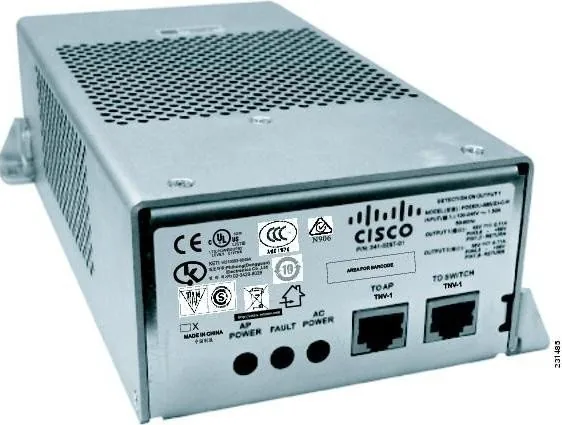
The Cisco Aironet PoE injector (AIR-PWRINJ1500-2=) is a compact PoE+ power injector designed to combine 56 VDC power with Ethernet data on a single shielded RJ-45 cable to power Cisco Aironet access points. Built for flexible wireless deployments, the unit delivers up to 80 W across four wire pairs and supports 10/100/1000Base-T connections. Ruggedized for outdoor-rated cabling and a wide operating temperature range, the injector is sized for convenient mounting on walls or other surfaces and includes LED indicators for AC power, AP power, and fault status.
The injector accepts 100–240 VAC input and provides tightly regulated 56 VDC output with a maximum current of 1.43 A. It requires shielded CAT5e or higher cabling between the switch and injector, and shielded outdoor-rated CAT5e or higher between the injector and access point. Cable recommendations include a minimum AP cable length of 10 ft (3 m) and a maximum end-to-end switch-to-AP length of 100 m (328 ft). The device must be mounted vertically for safety compliance and grounded using a minimum 12 AWG copper conductor for permanent installations.
Installation is straightforward: mount the injector using the elongated mounting tabs and appropriate fasteners, connect the TO SWITCH RJ-45 to your Ethernet switch, connect the TO AP RJ-45 to the access point (observing minimum cable length), and plug the AC cord into a suitable 100–240 VAC source. LEDs indicate operational state: AC POWER (green when powered), AP POWER (green when powering an AP), and FAULT (red on discovery or power-up error). The PoE-out port on the access point is disabled when using the external power injector.
Safety and regulatory guidance emphasize FCC Class B compliance, correct grounding, adherence to wiring gauges, and that only trained personnel should install or service the unit. The injector is not intended for installation in building environmental air spaces and must obey local mounting and electrical regulations. Documentation and support resources are available from Cisco for troubleshooting and service requests.
Notes:
- Use shielded, outdoor-rated CAT5e or higher cabling; AP cable 0.20–0.35 inch diameter recommended.
- Maintain AP cable length between 10 ft (3 m) and 140 ft (42 m); total switch-to-AP must not exceed 100 m (328 ft).
- Mount vertically and ground with minimum 12 AWG copper conductor.
Search for 67,706 Manuals online


Type-in Brand or Model