
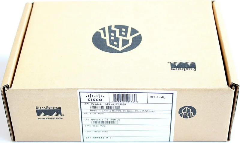
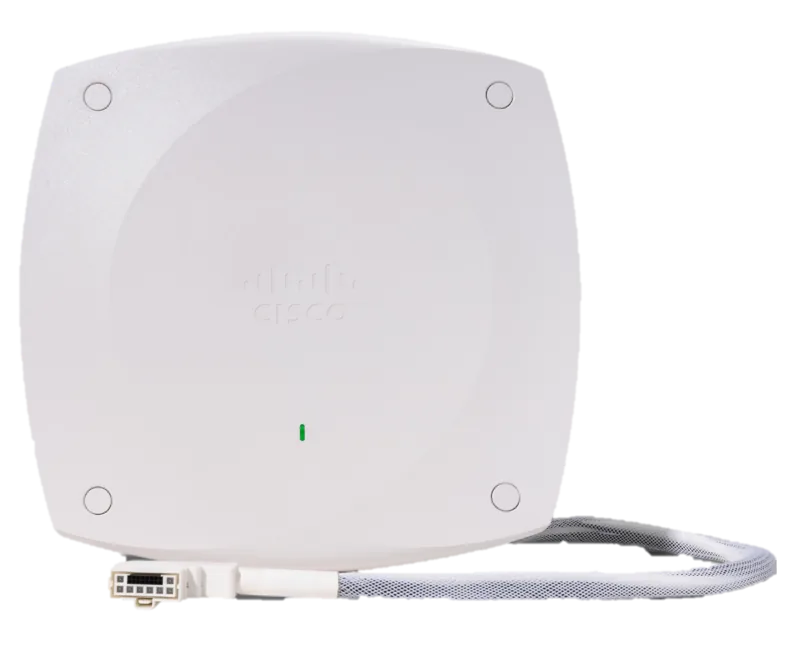
Cisco Aironet AIR-ANT5959 Manual
PDF manual · 20 Pages
English



Quick check
Incorrect answer, please try again.
Chat with your Cisco Aironet AIR-ANT5959 manual using AI
Get instant AI answers from your Cisco Aironet AIR-ANT5959 manual
Ask anything about the Cisco Aironet AIR-ANT5959. Answers come from this manual, with the pages they are based on.
Ask a Question
Do you recommend Aironet AIR-ANT5959?
Yes NoFrequently Asked Questions
This antenna operates within the 2400 to 2500 MHz band. This allows it to work with 2.4-GHz Cisco devices effectively for indoor wireless networking.
Is this answer helpful?
It must be mounted horizontally to maximize omnidirectional propagation characteristics. Vertical mounting may noticeably decrease range and overall performance. Place it at the center of the coverage area.
Is this answer helpful?
The antenna uses a Reverse-Polarity Threaded Naval Connector (RP-TNC) male type. It is compatible with Cisco Aironet radio products utilizing this specific connector interface.
Is this answer helpful?
Solid and pre-cast concrete walls limit signal penetration to one or two walls without degrading coverage significantly. Other materials like drywall allow penetration through five or six walls.
Is this answer helpful?
You should wear shoes with rubber soles, rubber gloves, and a long sleeved shirt or jacket. Do not use a metal ladder and ensure all power cables are identified.
Is this answer helpful?
You can resolve P3 and P4 issues yourself using the Cisco TAC Web Site. It provides online tools, knowledge bases, and software for self-service troubleshooting at any time.
Is this answer helpful?
The antenna comes with a 3 ft (0.9 mm) plenum rated cable. This length is sufficient for connecting to devices located within the standard ceiling grid space.
Is this answer helpful?
Advantages and Disadvantages
Advantages

- Operates at 2400 to 2500 MHz for reliable office connectivity
- Provides 2 dBi gain with omnidirectional coverage for wide area
- Compatible with Cisco Aironet radio products using RP-TNC connectors
- Designed for unobtrusive ceiling mounting in suspended track systems
- Includes plenum rated cable and straightforward installation clips
Disadvantages

- 2 dBi gain may be insufficient for very large coverage areas
- Must be mounted horizontally or range decreases significantly
- Metal obstructions like ducts interfere with signal strength
- Concrete walls limit signal penetration to one or two only
- Wire mesh or chain link acts as a harmonic reflector blocking signal
Product Specification
Type
omnidirectional
Application
WLAN
Frequency Range
2.4 GHz (2.4-2.5 GHz)
Antenna Gain (max.)
2 dBi @ 2.5 GHz
Impedance
50 Ohm
Connector
RP-TNC
Product Description
Maximizing Office Connectivity
In the modern workplace, consistent wireless access is vital for business operations. The Cisco Aironet Ceiling Mount Antenna, 2dBi omnidirectional Manual provides the necessary direction for installation and operation. This equipment is built for unobtrusive ceiling mounting. It ensures coverage without disrupting office aesthetics while maintaining performance standards expected in professional environments.
Performance Characteristics
This device operates in the 2400 to 2500 MHz band. It delivers a peak gain of 2 dBi with vertical linear polarization. The beamwidth is omnidirectional in the azimuth plane and 70 degrees in elevation. Nominal VSWR is 1.7:1. The connector is RP-TNC male. Length is 3 feet. Dimensions are 5.3 by 2.8 by 0.9 inches. Weight is 0.3 lbs. This configuration supports Cisco Aironet radio products utilizing the reverse-polarity threaded naval connector interface.
Setup Process
Mounting occurs on suspended ceiling tracks. Flush tiles allow direct clip attachment without modification. Recessed tiles need plastic adapters. Mark center point 2.5 inches from sides. Install adapters 5 inches apart. Align clips with track. Push gently until secure. Route cables above the grid and connect to the device. Replace tiles to finish. Trim material if necessary for cable accommodation. Horizontal mounting is mandatory to maximize omnidirectional propagation. Vertical placement reduces range and overall performance.
Interference Management
Keep distance from microwave ovens and 2-GHz cordless phones. These operate in the same frequency range and cause signal interference. Metal obstructions like ducts also reduce throughput. Wire mesh acts as a reflector blocking signals. Drywall permits signal through five or six walls. Concrete limits to one or two. Solid pre-cast concrete walls limit penetration significantly. Thick metal walls cause signals to reflect off and cause poor penetration. Chain link fences act as harmonic reflectors.
Safety Protocols
Plan your installation carefully and completely before you begin. Assume lines are electric until proven otherwise. Do not use metal ladders. Wear rubber soled shoes and gloves. Contact maintenance for unknown cables. If power lines are near, call emergency help immediately. Professional assistance is recommended for first-time users to ensure safety for yourself and others.
Technical Resources
Support is available via Cisco website. TAC Web Site resolves P3 and P4 issues regarding product capabilities. Escalation Center handles P1 and P2 for critical network issues. Online tools provide documentation. Registration allows full access to configuration. Access is free for registered users. This ensures network stability and quick resolution of any connectivity drops. Cisco.com provides interactive services for troubleshooting and training.
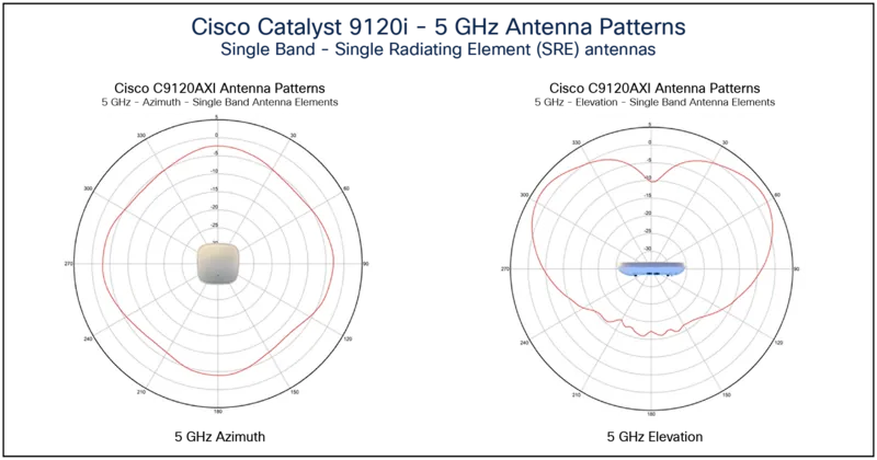
Optimizing signal propagation depends on correct placement. Following these steps ensures clear wireless communication throughout the facility. The radiation pattern includes detailed E-Plane and H-Plane patterns. These graphs visualize signal strength distribution. Utilizing these visual guides helps in accurate positioning.
Search for 67,706 Manuals online


Type-in Brand or Model