
CanaKit L298N Manual
PDF manual · 3 Pages
English



Quick check
Incorrect answer, please try again.
Chat with your CanaKit L298N manual using AI
Get instant AI answers from your CanaKit L298N manual
Ask anything about the CanaKit L298N. Answers come from this manual, with the pages they are based on.
Ask a Question
Do you recommend L298N?
Yes NoFrequently Asked Questions
The board supports a motor supply voltage typically between 6V and 35V DC. Ensure your motors and supply match this range and that current draw stays within the board’s per-channel limits.
Is this answer helpful?
Each channel can handle approximately 2A continuous for typical operation. Bridged mode can drive a single motor at higher current but requires careful thermal management and a capable power supply.
Is this answer helpful?
Yes. The onboard user-accessible 5V regulator can derive logic power from the motor supply (recommended). It provides about 1A for the L298 logic and additional circuits. Alternatively, you can disable the onboard regulator and supply an independent 5V input.
Is this answer helpful?
To brake: set ENA/ENB high and drive both direction inputs for that motor to the same logic level. To coast: set the corresponding enable pin (ENA/ENB) low, which lets the motor run freely.
Is this answer helpful?
CSA and CSB are current sense outputs tied to onboard high-power resistors. Use them with an ADC on your microcontroller to measure motor current, detect stalls, and implement protective responses.
Is this answer helpful?
Yes. The board includes eight Schottky EMF-protection diodes for back-EMF protection and a heatsink for thermal dissipation. Additional cooling may be necessary for sustained high-current use.
Is this answer helpful?
It can drive bipolar stepper motors using the dual H-bridges, but it does not provide advanced microstepping. For precise stepper control, pair it with appropriate step/direction control or choose a dedicated microstepping driver.
Is this answer helpful?
Advantages and Disadvantages
Advantages

- Independent control of two motors with up to 2A per channel.
- Onboard 5V regulator allows powering logic from motor supply (up to ~1A).
- Current sense outputs (CSA/CSB) enable stall detection and monitoring.
- Bridged mode supports higher-current single-motor operation.
- Integrated protection diodes, heatsink, LEDs, and screw terminals for reliability and convenience.
Disadvantages

- 2A per channel limits use with higher-current motors without additional cooling.
- Onboard 5V regulator shares heat with motor supply and may require external cooling under load.
- Bridged single-motor high-current operation needs careful thermal and supply considerations.
- Requires jumper configuration for different supply modes, which can be mis-set.
- Not suitable for precision microstepping without additional driver circuitry.
Product Specification
Manufacturer
Various
Type
Relay, Stepper Motor Driver, Control Board
Platform
Universal
Controller
L298N
Connection
Pin Header (4-Pin)
Power Supply
5.0.0-35.0V, 36 mA operation (max 2 A switching current)
Scope of Delivery
1x Module
Special Features
autonomous operation
Product Description
Dual H-Bridge L298N Stepper Motor Driver/Control Board Manual
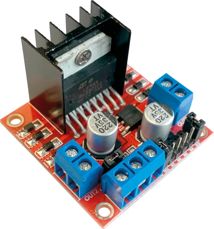
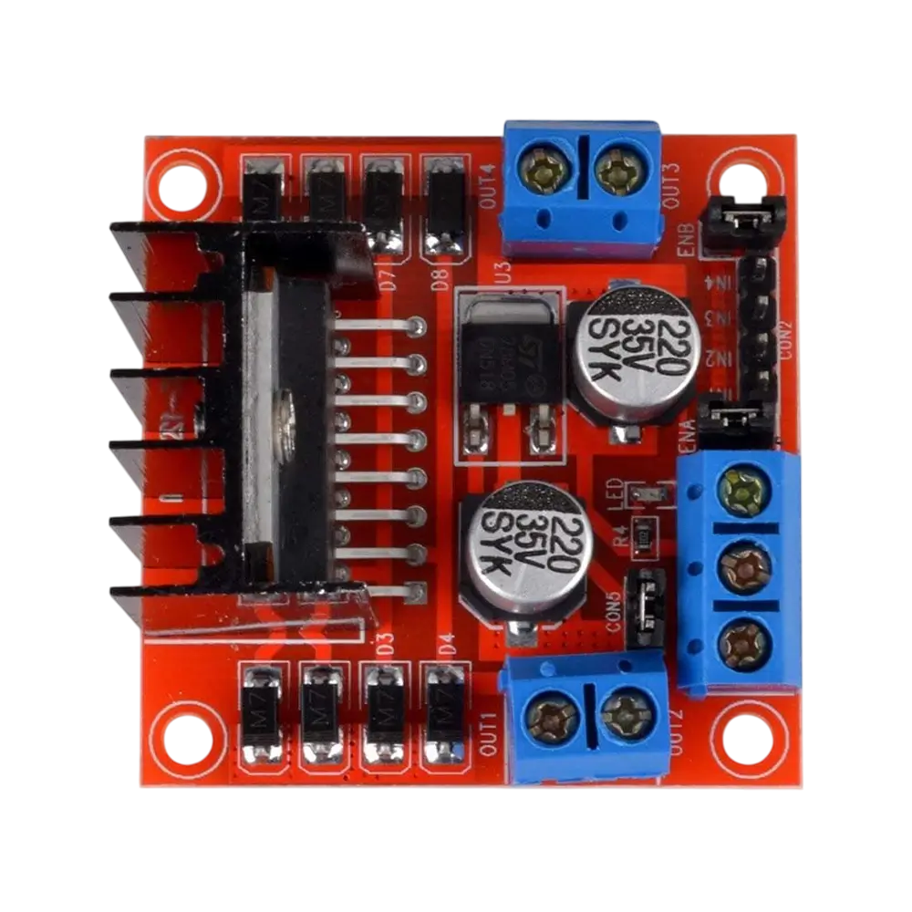
The Dual H-Bridge L298N Stepper Motor Driver/Control Board is a compact, robust driver designed to control two DC or stepper motors independently. Built around the widely used L298 dual H-bridge IC, this board supports two motors at up to 2A each and offers bridged mode to drive a single motor at higher currents. With integrated direction LEDs, a heatsink, screw terminals, Schottky EMF-protection diodes, and onboard high-power current sense resistors, it’s well suited for robotics, automation, and microcontroller-driven projects.
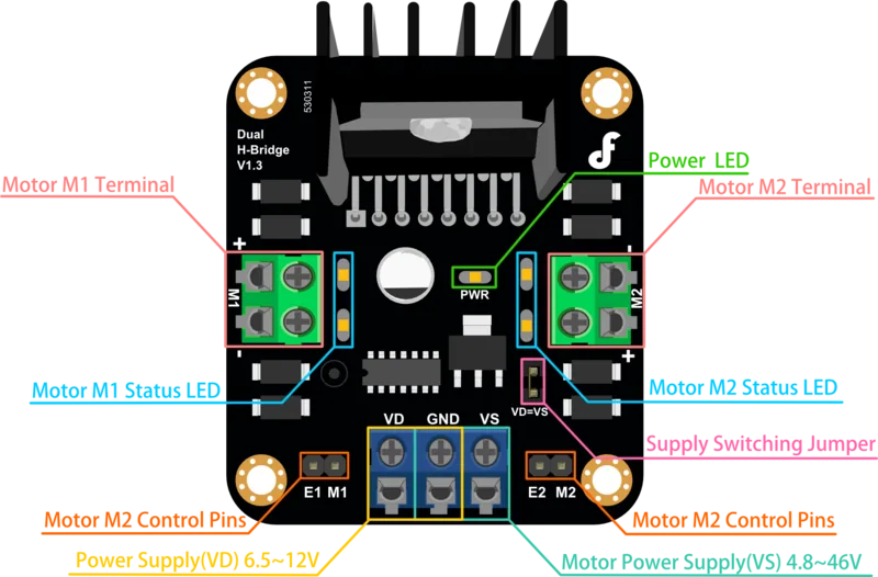
This driver provides flexible power arrangements. The onboard user-accessible 5V regulator can derive logic power from the motor supply (recommended), supplying up to about 1A for both the L298 logic and additional 5V circuits. Alternatively, you can disable the onboard regulator and feed a separate regulated 5V to isolate motor and logic supplies. Jumper settings enable easy switching between these modes.
Control is straightforward: each motor has an enable pin (ENA/ENB) and two direction inputs (IN1/IN2 for motor A, IN3/IN4 for motor B). Setting the enable high activates the motor; toggling the direction inputs determines rotation direction. Brake mode is achieved by enabling a motor and driving both direction pins to the same logic level. To let a motor coast freely, simply disable its enable pin. Two current sense outputs (CSA, CSB) provide real-time feedback of motor current via onboard sense resistors, useful for stall detection and protective routines.
The board’s design includes EMF protection and thermal considerations. Schottky diodes guard against back EMF spikes; a heat sink helps dissipate thermal load during continuous operation. Screw terminals simplify wiring for motors and power, while status LEDs offer quick visual feedback for direction and activity.
Whether you’re prototyping a robot, building a CNC axis, or driving stepper/DC motors from an MCU, this Dual H-Bridge L298N board balances ease-of-use with practical protection and monitoring features. Its ability to operate two motors independently or a single motor in bridged mode makes it versatile for a wide range of hobbyist and light industrial applications.
Notes
- Recommended motor supply: 6–35V DC. Observe current limits: 2A per channel continuous (single bridged motor higher current capability with caution).
- Use CSA/CSB outputs with ADC inputs to monitor current and implement stall detection.
- When using the motor supply to power the 5V regulator, ensure the regulator’s capacity matches your logic and peripheral needs.
- Respect proper cooling and consider external heat sinking for prolonged high-current use.
Search for 67,706 Manuals online


Type-in Brand or Model