
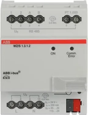
ABB WZ/S 1.3.1.2 Manual
PDF manual · 112 Pages
English



Quick check
Incorrect answer, please try again.
Chat with your ABB WZ/S 1.3.1.2 manual using AI
Get instant AI answers from your ABB WZ/S 1.3.1.2 manual
Ask anything about the ABB WZ/S 1.3.1.2. Answers come from this manual, with the pages they are based on.
WZ/S 1.3.1.2 Maintenance Schedule
Inspect the sensor at least twice a year for dirt and contamination. Clean if necessary to prevent false rain signals or wind sensor failure.
Switch off voltage supply before cleaning. Use a dry cloth or one dampened with soapy solution. Never use corrosive agents.
Free maintenance reminders
Timed to your purchase date. Always free, unsubscribe anytime.
Ask a Question
Do you recommend WZ/S 1.3.1.2?
Yes NoFrequently Asked Questions
No, the Weather Unit WZ/S 1.3.1.2 may not be mounted outdoors. It is designed for indoor installation within distribution boards.
Is this answer helpful?
A maximum of 107 communication objects, 254 group addresses and 254 associations can be linked with the Weather Unit.
Is this answer helpful?
It supports the Weather Sensor WES/A 3.1, WES/A 2.1 with GPS receiver, and WES/A 1.1 with DCF receiver for time synchronization.
Is this answer helpful?
The maximum permissible cable length between the Weather Unit and Weather Sensor is one hundred meters.
Is this answer helpful?
Yes, the value memory does not function without time synchronization using either GPS or DCF signals.
Is this answer helpful?
Yes, threshold limits can be modified via the bus interface dynamically without requiring physical access to the device.
Is this answer helpful?
If the sensor fails to send values, no output values are sent to the bus for sensors affected, but PT1000 values continue to be sent independently.
Is this answer helpful?
Advantages and Disadvantages
Advantages

- Supports up to eight independent weather data sources simultaneously
- Integrated power supply reduces complexity for sensor connection
- Configurable thresholds allow tailored responses per sensor type
- Four value memories enable long term historical trend analysis
- Easy commissioning process uses standard Engineering Tool Software ETS
Disadvantages

- Indoor mounting only prevents use in direct weather exposure
- Firmware updates may take approximately thirty minutes to complete
- Requires ETS software for physical address assignment and programming
- No facade control capabilities included in this specific module
- Backward compatibility has specific restrictions on older sensor models
Product Specification
Type
Control Unit
Standard
KNX
Function
Control, Temperature, Brightness, Rain, Wind Speed
Topology
Bus
Dimensions
2.83 x 3.54 x 2.54 in
Features
IP20
Product Description
Advanced Weather Monitoring Solutions for Smart Buildings
Intelligent KNX Weather Integration Systems
The ABB WZ/S 1.3.1.2 stands out as a robust modular installation device engineered for sophisticated environmental management within modern KNX networks. This central unit actively processes data from up to eight independent weather sources detected by specialized sensors such as the WES/A 3.1. By continuously recording critical variables including brightness levels across three directions, wind velocity, rainfall intensity, and ambient temperatures, the system automatically adapts room lighting and shading configurations. This dynamic adjustment meets individual occupant requirements while enhancing energy efficiency. Security protocols also leverage these metrics, automatically retracting blinds during high winds or closing skylights upon detecting rain events without human intervention. Autonomous calibration routines activate after startup ensuring measurement accuracy remains high throughout daily operations. This ensures optimal performance under varying climatic conditions experienced throughout the year.
Flexible Configuration and Logic Functions Available
System programming utilizes Engineering Tool Software ETS to customize operational parameters extensively according to site specific needs. Users define specific threshold limits for nearly every sensor input allowing tailored responses to changing weather conditions throughout seasons. Logical operations function as AND or OR gates supporting up to four distinct inputs per gate creating complex decision paths. Furthermore, four value memories preserve historical data points in a ring buffer structure enabling long term trend analysis for facility managers. Status LEDs provide visual confirmation regarding mains voltage presence and bus communication errors ensuring operators remain informed of system health instantly. The unit integrates seamlessly with mains voltage supplies ranging from eighty-five to two hundred sixty-five volts alternating current drawing minimal power from the line itself reducing overall energy consumption significantly. Thresholds themselves can be modified via the bus interface dynamically without requiring physical access. Communication objects facilitate remote monitoring through standardized group addresses supporting diverse integration requirements effectively.
Installation Requirements and Technical Limitations Defined
Important safety instructions warn against outdoor mounting due to protection type ratings. Mounting occurs within distribution boards utilizing standard thirty-five millimeter rails occupying four space units of width making it compatible with existing infrastructure layouts easily. Maximum permissible cable lengths extend one hundred meters between the central unit and external weather sensor assembly providing significant flexibility for large installations. Location selection demands careful consideration to avoid signal interference from nearby electrical loads which might disrupt global positioning satellite reception required for time synchronization accuracy. Backward compatibility exists with earlier sensor models though functional limitations apply depending on hardware generation used in the field. Facade control capabilities require alternative equipment rather than this specific module limiting certain application types. Regular maintenance checks verify cleanliness preventing false alarms caused by accumulated dirt on sensitive detection surfaces especially regarding rain sensing elements. The device features internal logic configuration options which allow users to link inputs together via logic functions for enhanced automation scenarios.
Search for 67,706 Manuals online


Type-in Brand or Model