auf KNX zugreifen. Die USB Schnittstelle unterstützt
„Long Frames“. Der KNX Teil und der USB Teil sind
galvanisch voneinander getrennt. Solange USB nicht
angeschlossen ist, ist die Schnittstelle ohne Funk-
tion.
DE
FREN
Montage- und Betriebsanleitung
Installation and Operating Instructions
Mode d´emploi
Instrucciones de montaje de servicio
Istruzioni per l´uso
Montage- en bedieningshandleiding
Instrukcja montażu i eksploatacji
Руководство по монтажу и эксплуатации
安装和操作手册
USB/S 1.2
DE
USB-Schnittstelle
EN
USB Interface
FR
Interface USB
ES
Interfaz USB
IT
Interfaccia USB
NL
USB-Interface
PL
Interfejs USB, MDRC
RU
USBинтерфейс,MDRC
CN
USB接口模块,标准导轨安装
2CDG941201P0001
IP20
-5 °C
+45 °C
Bedienung und Anzeige
ON
- Die LED leuchtet dauerhaft, wenn USB ange-
schlossen ist.
USB
- Die LED leuchtet dauerhaft, wenn USB ange-
schlossen ist. Bei USB Datenverkehr blinkt die LED.
KNX
- Die LED leuchtet dauerhaft, wenn USB und KNX
angeschlossen sind. Bei KNX Datenverkehr blinkt
die LED.
LED/Taste KNX Programmierenb c
- Keine Funktion
Montage
Das Gerät ist geeignet zum Einbau in Verteilern oder
Kleingehäusen für Schnellbefestigung auf 35 mm
Tragschienen, nach DIN EN 60715. Die Zugänglichkeit
des Gerätes zum Betreiben, Prüfen, Besichtigen, War-
ten und Reparieren muss gemäß DIN VDE 0100-520
sichergestellt sein.
Anschluss
Die Verbindung zum Bus erfolgt über die mitgelieferte
Busanschlussklemme. Die Verbindung zu USB wird
über die USB Buchse Typ B hergestellt.
Inbetriebnahme
Die physikalische Adresse wird in der ETS lokal ein-
gestellt. Es ist kein Applikationsprogramm erforderlich.
Reinigen
Verschmutzte Geräte können mit einem trockenen oder
leicht mit Seifenlauge angefeuchteten Tuch gereinigt
werden. Auf keinen Fall dürfen ätzende Mittel oder
Lösungsmittel verwendet werden.
Wartung
Das Gerät ist vor dem Reinigen spannungsfrei zu
schalten. Das Gerät ist wartungsfrei. Bei Schäden (z.B.
durch Transport, Lagerung) dürfen keine Reparaturen
vor genommen werden.
Beim Öffnen des Gerätes erlischt der Gewährleistungs-
anspruch!
Eine ausführliche Beschreibung der Parametrierung
und Inbetriebnahme finden Sie in der technischen
Dokumentation des Gerätes. Diese finden Sie zum
Download im Internet unter www.abb.com/knx.
Wichtige Hinweise
Achtung! Installation nur durch elektrotechnische
Fachkraft. Bei der Planung und Errichtung von elek-
trischen Anlagen sowie von sicherheitstechnischen
Anlagen für Einbruch- und Branderkennung sind die
einschlägigen Normen, Richtlinien, Vorschriften und
Bestimmungen des jeweiligen Landes zu beachten.
– Gerät bei Transport, Lagerung und im Betrieb vor
Feuchtigkeit, Schmutz und Beschädigung schüt-
zen!
– Gerät nur innerhalb der spezifizierten technischen
Daten betreiben!
– Gerät nur im geschlossenen Gehäuse (Verteiler)
betreiben! Das Gerät darf nicht geöffnet werden.
ES
1
7
8
9
2
3
4
6
36
Technical data (extract)
Supply voltage
KNXVia ABB i-bus
®
KNX
(21…30 V DC)
USBUSB 1.1 (5 V DC)
Max. cable length 5 m
Current consumption
KNXMax. 3 mA
USBMax. 15 mA
Total power dissipationMax. 200 mW
Temperature range
In operation (T
u
) -5°C ... +45°C
Storage-25 C ... +55 C
Transport-25 C ... +70 C
Degree of protectionIP20 to EN 60 529
Protection classII to EN 61 140
Overvoltage category
III to EN 60 664-1
Pollution degree2 to EN 60 664-1
Atmospheric pressureAtmosphere up to 2,000 m
Maximum air humidity95%, no condensation
allowed
Dimensions (H x W x D)
2 space units
90 x 36 x 63.5 mm
Device connection
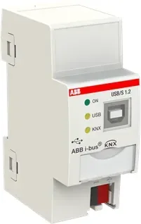
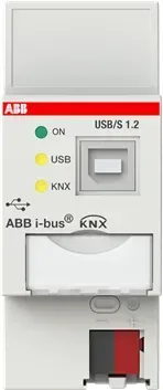
a Label carriers
bKNX programming LED (red) (no function)
cKNX programming button (no function)
d Bus connection terminal
e Cover cap
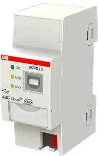
ON LED (green)
USB LED (yellow)
KNX LED (yellow)
USB Type B connector
Device description
The USB/S 1.2 USB Interface enables communication
between ETS and a KNX system (programming, bus
monitoring, group monitoring). It also allows display
systems to access KNX via USB. The USB interface
supports Long Frames. The KNX and USB parts are
electrically isolated from each other. The USB must be
connected for the interface to function.
Operation and display
ON
- The LED lights up steady when the USB is
connected.
USB
- The LED lights up steady when the USB is
connected. It flashes when USB data traffic is
present.
KNX
- The LED lights up steady when the USB and KNX
are connected. It flashes when KNX data traffic is
present.
KNX Programming LED/button b c
- No function
Mounting
The device is suitable for fast installation in distri-
bution units or small housings on 35 mm mounting
rails to EN 60715. Accessibility of the device for
the purpose of operation, testing, visual inspection,
maintenance and repair must be provided compliant
to DIN VDE 0100-520.
Connection
The interface connects to the bus via the supplied bus
connection terminal and to the USB via the USB Type
B connector.
Commissioning
The physical address is set locally in ETS. No applica-
tion program is required.
Cleaning
If devices become dirty, they can be cleaned using a dry
cloth or a cloth dampened with a soapy solution. Never
use corrosive agents or solutions.
Maintenance
Disconnect the device’s power supply before cleaning.
The device is maintenance-free. In the event of damage
(e.g., during transport or storage), repairs should only
be carried out by an authorized person.
Opening the device voids the warranty.
For a detailed description of parametrization and com-
missioning, please refer to the technical documenta-
tion for the device, which is available for download at
www.abb.com/knx.
Important notes
Caution! Installation by qualified electricians only. The
applicable standards, directives, regulations and spec-
ifications for the country in question must be observed
when planning and setting up electrical installations
and security systems for intrusion and fire detection.
– Protect the device against damp, dirt and damage
during transport, storage and operation.
– Do not operate the device outside the specified
technical data.
– Only operate the device in a closed housing (distri-
bution unit). Do not open the device.
Caractéristiques techniques (extrait)
Tension d'alimentation
KNXpar ABB i-bus
®
KNX
(21...30 V CC)
USBUSB 1.1 (5 V CC)
Longueur de ligne max. 5 m
Courant consommé
KNXmax. 3 mA
USBmax. 15 mA
Puissance dissipée totalemax. 200 mW
Plage de températures
En fonctionnement (T
u
) -5 °C ... +45 °C
Stockage-25 °C ... +55 °C
Transport-25 °C ... +70 °C
Indice de protectionIP20 selon EN 60 529
Classe de protectionII selon EN 61 140
Classe de surtension
III selon EN 60 664-1
Degré de contamination2 selon EN 60 664-1
Pression atmosphériqueAtmosphère jusqu'à
2 000 m
Humidité relative
maximale
95 %, aucune condensation
admissible
Dimensions (h x l x p)
2 TE, 90 x 36 x 63,5 mm
Raccordement de l'appareil
a Porte-étiquette
b LED Programmation KNX (rouge) (sans fonction)
c ToucheProgrammation KNX (sans fonction)
d Borne de raccordement du bus
e Couvercle
LED MARCHE (verte)
LED USB (jaune)
LED KNX (jaune)
Port USB de type B
Description de l'appareil
L’interface USB USB/S 1.2 permet la communication
entre l’ETS et une installation KNX (programmation,
moniteur de bus, moniteur de groupe). Une visuali-
sation peut également accéder au KNX via USB. L’in-
terface USB prend en charge les " Long Frames ". La
partie KNX et la partie USB sont isolées galvanique-
ment. L’interface est dépourvue de fonction tant que le
raccord USB n’est pas effectué.
Utilisation et affichage
MARCHE
- La LED s’allume en continu une fois le raccord USB
effectué.
USB
- La LED s’allume en continu une fois le raccord USB
effectué. La LED clignote lors du trafic de
données USB.
KNX
- La LED s’allume en continu une fois les
raccords USB et KNX effectués. La LED clignote lors
du trafic de données KNX.
LED/ToucheProgrammation KNXb c
- Aucune fonction
Montage
L'appareil est destiné à être monté rapidement dans
un coffret de distribution ou un coffret de petite taille
sur rails de 35 mm selon EN 60715. L'accessibilité de
l'appareil pour le fonctionnement, le contrôle, la super-
vision, l'entretien et la réparation doit être assurée en
vertu de la norme DIN VDE 0100-520.
Raccordement
Le raccordement au bus est réalisé via la borne de
raccordement du bus fournie Le raccordement USB
s'effectue à l'aide du port USB de type B.
Mise en service
L’adresse physique est paramétrée de manière locale
dans l’ETS. Aucun programme d’application néces-
saire.
Nettoyage
Les appareils encrassés peuvent être nettoyés avec
un chiffon sec ou un chiffon humidifié dans de l'eau
savonneuse. L'usage d'agents caustiques ou de solvants
est absolument proscrit.
Maintenance
L'appareil doit être mis hors tension avant le nettoyage.
L'appareil ne nécessite aucun entretien. En cas de
dommages (survenus p. ex. pendant le transport ou
le stockage), aucune réparation ne doit être effectuée.
L'ouverture de l’appareil entraîne l'annulation de la
garantie !
Vous trouverez une description détaillée du paramé-
trage et de la mise en service dans la documentation
technique de l'appareil. Vous pouvez télécharger celle-
ci en ligne à l'adresse www.abb.com/knx.
Remarques importantes
Attention ! Installation uniquement par des personnes
qualifiées en électrotechnique. Lors de la planification
et de la construction d'installations électriques, d'ins-
tallations relatives à la sécurité, intrusion et protection
incendie, les normes, directives, réglementations
et dispositions pertinentes en vigueur dans le pays
concerné doivent être respectées.
– Protéger l'appareil contre la poussière, l'humidité
et les risques de dommages lors du transport, du
stockage et de l'utilisation.
– N'utiliser l'appareil que dans le respect des don-
nées techniques spécifiées.
– N'utiliser l'appareil que dans un boîtier fermé
(coffret de distribution). L'appareil ne doit pas être
ouvert.
Datos técnicos (extracto)
Tensión de alimentación
KNXMediante ABB i-bus
®
KNX
(21...30 V CC)
USBUSB 1.1 (5 V CC)
máx. longitud de cable 5 m
Consumo de corriente
KNXMáx. 3 mA
USBMáx. 15 mA
Potencia disipada totalMáx. 200 mW
Rango de temperaturas
En servicio (T
u
) -5 °C- +45 °C
Almacenamiento-25 °C- +55 °C
Transporte-25 °C- +70 °C
Tipo de protecciónIP20 según EN 60 529
Clase de protecciónII según DIN EN 61 140
Categoría de sobretensión
III según DIN EN 60 664-1
Grado de contaminación2 según DIN EN 60 664-1
Presión del aireAtmósfera hasta 2.000 m
Humedad máxima del
aire
95 %, no admite rocío
Dimensiones (H x A x P)
2 HP, 90 x 36 x 63,5 mm
Conexión del aparato
a Portaletreros
b LED Programar KNX (rojo) (sin función)
c Tecla Programar KNX (sin función)
d Borne de conexión de bus
e Tapa
LED ON (verde)
LED USB (amarillo)
LED KNX (amarillo)
Conector USB tipo B
Descripción del aparato
La interfaz USB USB/S 1.2 permite la comunicación
entre el ETS y una instalación KNX (programación,
monitor de bus, monitor de grupos). Una visualización
también puede acceder a KNX a través de USB. La
interfaz USB es compatible con «Long Frames». Las
partes KNX y USB están separadas la una de la otra
galvánicamente. Mientras el USB no esté conectado, la
interfaz no tiene función.
Manejo e indicación
ON
- El LED se ilumina de forma permanente cuando USB
está conectado.
USB
- El LED se ilumina de forma permanente cuando USB
está conectado. El LED se ilumina si existe tráfico de
datos de USB.
KNX
- El LED se ilumina de forma permanente cuando USB
y KNX están conectados. El LED se ilumina si existe
tráfico de datos de KNX.
LED/tecla Programar KNXb c
- Sin función
Montaje
El aparato está diseñado para el montaje en distri-
buidores o pequeñas carcasas para montaje rápido
en raíles de 35 mm, según DIN EN 60715. Debe ga-
rantizarse la accesibilidad del aparato para operarlo,
comprobarlo, inspeccionarlo, mantenerlo y repararlo
según DIN VDE 0100-520.
Conexión
La conexión con el bus se realiza mediante los bornes
de conexión de bus suministrados. La conexión a USB
se realiza mediante un conector USB tipo B.
Puesta en marcha
La dirección física se introduce en el ETS local. No se
requiere ningún programa de aplicación.
Limpieza
Los aparatos sucios pueden limpiarse con un paño seco
o con un paño humedecido en solución jabonosa. Está
prohibido utilizar productos cáusticos o disolventes.
Mantenimiento
Antes de la limpieza debe desconectarse la tensión
del aparato. El aparato no requiere mantenimiento.
En caso de daños (por ejemplo, durante el transporte,
almacenamiento), no está permitida su reparación.
Al abrir el aparato se extingue el derecho a garantía.
En la documentación técnica del aparato encontrará
una descripción detallada de la parametrización y de la
puesta en marcha. Dicha documentación está disponi-
ble para su descarga en Internet en www.abb.com/knx.
Indicaciones importantes
Atención. La instalación deberá ser realizada única-
mente por electricistas especializados. Para planificar
y montar instalaciones eléctricas, así como instalacio-
nes técnicas de seguridad para la detección de robo
e incendio, deben observarse las normas, directivas,
reglamentos y disposiciones del país correspondiente.
– El dispositivo debe protegerse contra la humedad,
la suciedad y los daños durante el servicio, el
transporte y el almacenamiento.
– El aparato debe funcionar solo respetando los da-
tos técnicos especificados.
– El aparato solo debe funcionar dentro de la carcasa
cerrada (distribuidor). El aparato no debe abrirse.
/2
%
Quick check
I'm not a robot
Incorrect answer, please try again.
Chat with your ABB USB/S 1.2 manual using AI
Get instant AI answers from your ABB USB/S 1.2 manual
Ask anything about the ABB USB/S 1.2. Answers come from this manual, with the pages they are based on.
Ask a Question
0/1000
Do you recommend USB/S 1.2?
YesNo
Frequently Asked
Questions
A
No separate application program is required for initial commissioning. The physical address is set locally within the Engineering Software tool for standard operations without needing extra software packages.
Is this answer helpful?
A
You may clean dirty devices using a dry cloth or a cloth dampened with a soapy solution. Never use corrosive agents or solvents as these can damage the casing and internal components permanently.
Is this answer helpful?
A
Repairs should not be carried out by users. If damage occurs, it should only be handled by authorized persons. Opening the device yourself voids the warranty claim immediately and invalidates coverage.
Is this answer helpful?
A
The KNX power supply comes via ABB i-bus at 21 to 30 volts direct current. The USB connection operates at 5 volts direct current with a maximum cable length of 5 meters.
Is this answer helpful?
A
No, the KNX part and the USB part are galvanically isolated from each other. This separation ensures that electrical faults on one side do not damage the other connected system.
Is this answer helpful?
A
The device is suitable for fast installation on 35 mm mounting rails. It fits into distribution units or small housings following DIN EN 60715 standards for accessible placement.
Is this answer helpful?
A
The green LED lights steady when USB is connected. The yellow USB LED flashes during USB traffic. The yellow KNX LED lights steady when both connect and flashes during KNX traffic.
Is this answer helpful?
M: QW-35-FL
Advantagesand
Disadvantages
Advantages
Galvanic isolation protects PC and KNX network from electrical surges and interference
Compact 2TE size fits easily into standard distribution boards and small housings
Supports Long Frame protocols for efficient data transfer between ETS and system
Low power consumption ensures energy efficiency during continuous operation cycles
Simple LED indicators provide clear visual feedback on power and traffic status
VS
Disadvantages
Interface ceases to function if the USB connection is not physically attached
Warranty becomes void immediately if the user opens the protective housing casing
USB cable length is strictly limited to a maximum of five meters for signal integrity
Device is maintenance free but cannot be repaired internally by unauthorized personnel
Must be operated exclusively inside a closed enclosure for safety and compliance reasons
M: QW-35-FL
Product
Specification
Type
Function Module
Interface
KNX, USB
Function
Interface Expansion
Topology
Bus
Dimensions
1.42x3.54x2.54in
Features
IP20
M: QW-35-FL
Product
Description
Essential Building Automation Tool
Explore the versatile features of the ABB USB/S1.2 KNX USB Interface, 2TE REG Function Module Manual. This device acts as a robust gateway for connecting personal computers to KNX bus systems. It facilitates essential programming functions for Electricians using standard Electronic Training Software tools. Direct linkage supports comprehensive bus monitoring capabilities. Visual display systems can also interface with the KNX network effortlessly through this dedicated hardware component. The design supports Long Frame protocols for enhanced data handling efficiency. Crucially, the KNX portion and USB portion are galvanically isolated to protect connected equipment from electrical noise and surges.
Technical Parameters and Power
Supply voltage originates from the KNX wiring delivering twenty-one to thirty volts direct current. The USB port operates at five volts direct current with a maximum cable length of five meters. Current consumption remains efficient at three milliamperes on the KNX side and fifteen milliamperes on the USB side. Total power dissipation rarely exceeds two hundred milliwatts. Temperature stability is maintained between negative five degrees Celsius plus forty-five degrees Celsius during operation. Storage conditions allow wider ranges down to negative twenty-five degrees Celsius. Humidity must stay below ninety-five percent with no condensation allowed to prevent damage.
Installation and Maintenance
Mounting utilizes thirty-five millimeter mounting rails according to European safety standards. Device occupies two standard track units in size. Enclosed cabinet housing is mandatory for safe operation within industrial settings. The unit remains maintenance-free throughout its lifecycle but requires regular visual inspections. Cleaning involves a dry cloth or one dampened with soapy water. Never use corrosive agents or solvent cleaners. Before cleaning, disconnect power completely. Opening the case voids all warranty coverage immediately. Damage from transport or storage should never be repaired by users.
Indicators and Commissioning
Status LEDs offer immediate feedback on connection states. Green light confirms power connection presence. Yellow USB indicator flashes when data traffic passes through the interface. Another yellow light indicates active KNX data packets moving across the bus. Physical addresses configure locally within the Engineering Software tool. No separate application programs are required for initial commissioning steps. Refer to online documentation for deep parametric adjustments if advanced configurations arise.
Important Safety Notice
Always follow local electrical regulations and norms during planning phases. Qualified personnel must perform all installation work to ensure compliance with safety directives. Do not operate outside specified technical data ranges. Protect against moisture dirt and mechanical shocks. This interface simplifies automation setup while maintaining high reliability standards.