Chat with your ABB SV/S 30.640.5.1 manual using AI
Get instant AI answers from your ABB SV/S 30.640.5.1 manual
Ask anything about the ABB SV/S 30.640.5.1. Answers come from this manual, with the pages they are based on.
Ask a Question
0/1000
Do you recommend SV/S 30.640.5.1?
YesNo
Frequently Asked
Questions
A
You can trigger a reset manually by pressing the front panel button for over two seconds or digitally by sending a telegram to the Trigger bus reset object via the KNX network.
Is this answer helpful?
A
The device outputs a rated voltage of 30 V DC SELV for the KNX bus line to power connected components safely.
Is this answer helpful?
A
Yes, compatible sealed lead-acid batteries can be connected to extend runtime during mains failures for up to several hours depending on the battery size and load.
Is this answer helpful?
A
Mount the device on a standard 35 mm mounting rail inside an enclosed distribution board complying with safety regulations.
Is this answer helpful?
A
Yes, it includes short-circuit and overload monitoring with automatic current limiting or shutdown if thresholds are exceeded continuously.
Is this answer helpful?
A
The minimum distance between two units is defined but the total KNX bus line length can reach up to 200 meters with proper planning.
Is this answer helpful?
A
Specific versions like SV/S 30.320.2.1 and SV/S 30.640.5.1 include extended diagnostic functions compared to standard power supply types.
Is this answer helpful?
M: QW-35-FL
Advantagesand
Disadvantages
Advantages
Detailed diagnostic feedback via KNX telegrams
Multiple LED indicators for quick visual status checks
Remote reset capability through software or button
Backup battery support for uninterrupted power during outages
Integrated choke protection against short circuits and overloads
VS
Disadvantages
Requires specialized Engineering Tool Software for configuration
Non-isolated secondary output requires external choke for extra line
Auto-shutdown occurs if internal temperature exceeds safe limits
Reset functionality inactive during software programming phase
Maximum cable distance limited to 200 meters per line
M: QW-35-FL
Product
Specification
Type
Power Supply
Standard
KNX
Function
Power Supply
Dimensions
2.83 x 3.54 x 2.54 in
Features
IP20
M: QW-35-FL
Product
Description
Optimizing KNX Systems with Advanced Power Solutions
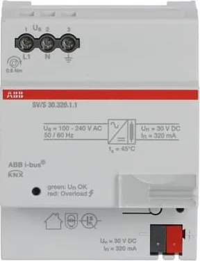
Modern building automation relies heavily on reliable energy sources to function effectively throughout the day and night. The ABB i-bus series offers robust solutions designed specifically for continuous operation in demanding environments. Among these offerings, the units equipped with diagnostic capabilities stand out for their enhanced monitoring features that go beyond simple power delivery. These devices manage system voltage meticulously and provide critical feedback through integrated communication channels accessible to all KNX nodes.
When deploying these units, understanding the configuration is absolutely vital for system integrity. Many technicians reference detailed information similar to the ABB KNX Power Supply with Diagnostic Function 30V Manual during initial setup procedures to ensure accuracy. Although physical documentation styles vary globally, the core principles regarding voltage regulation and current limits remain consistent across regions. The output voltage is strictly maintained at 30 V DC SELV, ensuring electrical safety across all connected components regardless of load fluctuations. Bus lines receive regulated power through built-in decoupling chokes which actively protect against dangerous short circuits and persistent overloads.
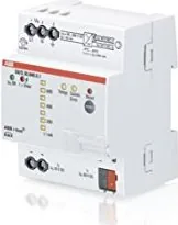
Advanced models allow for detailed tracking via standard KNX telegrams rather than simple binary signals alone. Status messages indicate precise bus current consumption and line health status instantaneously. Visual indicators include a variety of LEDs showing different operational states clearly. Green lights consistently signal normal function and available power, while red alerts notify operators immediately of potential overload conditions requiring attention. Yellow LEDs assist in quantifying current flow levels across various predefined thresholds for accurate diagnostics. This granular visibility helps maintain overall network stability before minor faults escalate into major outages affecting facility operations.
Physical installation occurs on standard 35 mm mounting rails within enclosed distribution boards. Electrical specialists must perform all commissioning tasks to ensure full compliance with local safety regulations and directives. Parameters can be easily adjusted using dedicated Engineering Tool Software interfaces. Users configure cyclic send values and request status objects remotely through the application layer. Reset functions exist both physically on the front panel and digitally via bus commands when mains voltage is present.
Safety mechanisms include automatic shutdown logic upon detecting internal overheating exceeding 100 degrees Celsius. Mandatory cooling periods are required before attempting to restart after significant fault conditions occur. Backup battery options extend runtime significantly during mains failure events protecting connected sensors. Planning applications involve checking voltage drop calculations over distances up to 200 meters maximum. Proper spacing prevents electromagnetic interference between multiple power supply units installed on the same trunk line. These specifications help engineers calculate load capacities accurately.